
| Pin No | Function |
| 1 & 7 | Output for First OP-AMP |
| 2 & 6 | It inverts the signals by 180 degrees i.e., if applied signal is of -5V then we will get the output of same signal as +5V. |
| 3 & 5 | it does not invert the signal, i.e., if applied signal is of +5V then in the output also we get same voltage |
| 4 | It is used for ground |
| 8 | Vcc |
What is an operational Amplifiers?
Automatic battery charger circuit:
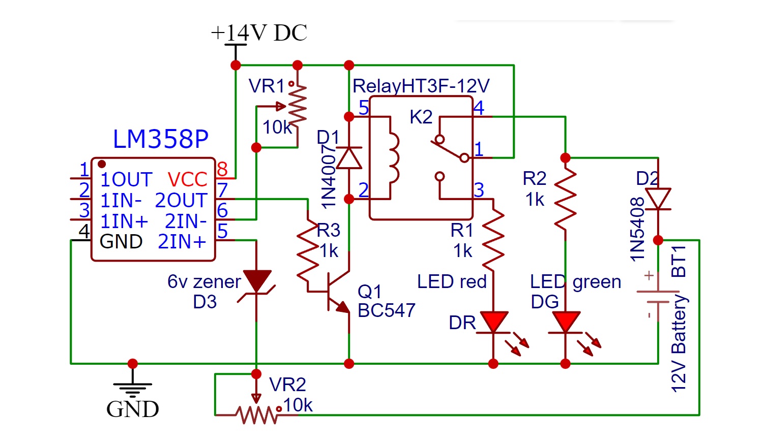
Components:
- R1, R2, R3 1k (1/4watt)
- VR1, VR2 10k potentiometer
- HT3F-12V Relay
- D11N4007
- D2 1N5408
- D3 1 n5233B (6V Zener)
- 第一季度BC547
- U1LM358
- DG LED (green)
- DR LED (red)
- 12V battery
Working of automatic battery charger circuit:
First of all, the 220V AC is stepped down by transformer to 15V. Then it is rectified and smoothen by capacitor C1. It is regulated to 14V by using voltage regulator Lm317. Then it is fed to the battery charging circuit. To set the Battery charging threshold voltage, LM358 and two potentiometers (or trimmer) have been used. We apply a reference voltage on the inverting pin of LM358. The threshold voltage is applied at the non-inverting pin of the opamp. If Battery charges up to threshold voltage, opamp will turn on the transistor and it will act as the switch and relay will be energized.
This happens as the battery charges the potential across the Zener Diode increase. The potentiometer is set such as that exactly at threshold voltage the Zener breakdown occurs, and Zener Diode starts conducting making output of OP-AMP high. This cuts power supply to the battery.
During the charging process, green LED glows which indicates that the battery is charging. When the battery gets fully charged its voltage reaches the threshold voltage, this voltage changes the output of the OP-AMP to high. This changes the position of the relay. Hence, switch off the circuit but RED LED will glow pointing to the completion of charging.
How to set the battery charger circuit cutoff threshold:
Initially keep the power to the circuit switched OFF.
Connect a variable DC power supply source across the battery points of the circuit.
Apply a Voltage that equals to the cutoff threshold voltage of the battery. Then adjust RV1 so that relay just activates, that is the cut-off voltage.
For a 12V battery, it is nearly 13V and for a Li-Po battery, it is 4.35V.
To charge Li-Po battery you can use this5V charger circuit
The setting up of the circuit is done.
Remove the external variable voltage source and replace it with a battery for charging purposes.
Variable Power Supply Circuit:
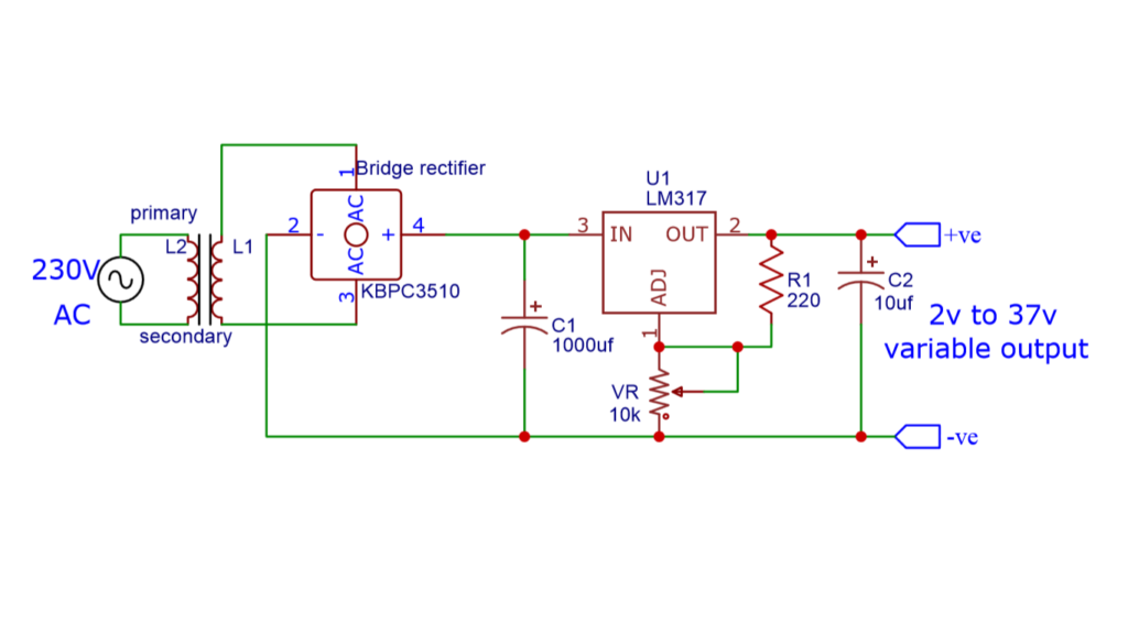
The above circuit is a variable power supply circuit. This circuit can give an output voltage ranging from 1 or 2 to 37 volts and an output current up to 3A. you can use the above circuit to make a variable power supply.
Working of the circuit:
The transformer used in the above circuit is having a 15V, 3A output. Then we have used the KBPC3510 rectifier to rectify the AC output oftransformer. The rectifier converts Sinusoidal AC into a unidirectional DC pulsating Voltage having AC component and fluctuations.
A 1000ufpolar capacitoris used to smooth out the DC supply. After this, by using IC LM317 the DC output is controlled. By using the 10k potentiometer the output DC voltage can be controlled. Further, the 10uf cap is used for a varying load.
Components:
- T1 15V Transformer (3A)
- KBPC3510 Bridge diode
- C1 1000uF (25V electrolytic)
- C2 10uF (non-polar)
- R1 220Ω
- VR 10kΩ
- LM317 IC
Hi
Can you explain the function of RV2?
Also is the value of the Zener diode critical?
I am trying to charge an old 9Volt battery from a Solar panel.
I have seen many circuit ideas 555 timer 741 op amp all with Zener diodes but nobody addresses the value of the Zener. ie should it be changed depending on battery voltage.
Thanks
Mike
yes it should be according to the battery specifications
How should I convert this charger to charge for 24 V .
Yes